Sharing our passion for the Jeep life!
Steering
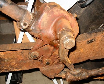
The Ross cam and lever steering system was used on CJs from '46-'71. While functional and effective for its time, it has some distinct disadvantages when compared to the modern steering systems used in later vehicles. The Ross system relies on a manual steering box (mounted to the frame below the firewall) and a complex mix of bellcranks, pivot points, and linkages that allows for excessive play and wandering. The multiple pivot points are wear items that frequently need to be rebuilt or replaced. Even when factory fresh, the design allowed for a lot of wander.
(Sidebar: With the removal of the Ross steering, I wanted to also remove the obsolete bellcrank mounting bracket for a cleaner-looking frame. The bracket was mounted to the frame crossmember via several large OEM rivets. It was time consuming, but I ground down each rivet head flush with the frame and then heated them with a small torch and drove them out one by one.)
The Saginaw steering gearboxes, introduced to the Jeep line in 1972, have proven themselves to be extremely rugged and durable. Add to that the simpler steering linkage design of later CJs that use a single tie rod and a draglink, and the benefits are clear. The most common replacement for the Ross system is a later model Saginaw steering box (manual or power) mounted out front on the driver side frame horn just behind the front bumper, and there are several kits available to facilitate this. This is a stellar improvement over the Ross system.
While researching options, I stumbled upon an alternative that I felt would be ideal for my application. Herm the Overdrive Guy offers a kit that facilitates mounting of a Ford reverse rotation steering box behind the front crossmember. The kit includes a heavy duty mounting bracket, required hardware, and a Pitman arm with the correct taper. The Ford reverse rotation steering gearboxes were used on F150/250/350 full-size pickups, vans, and compact Rangers, and they are heavy duty, plentiful, and relatively inexpensive. This setup mounts the steering box to the strongest part of the frame, where it is fully boxed, providing a very solid mounting point. Herm stated that this kit will work with the Dauntless V6 and the Sanderson aftermarket headers, so I decided to give it a try.

Unfortunately, after months of trial and error using multiple setup positions, custom pillow block brackets, single and double u-joint connections, and various lengths of double-D steering shaft sections, I gave up on this setup altogether. I like the idea of the reverse rotation setup, and I've seen examples of it successfully installed on 4-cylinder flatfenders, but it would not work on my V6 project. No matter what I tried, even with the steering shaft angles within spec, I couldn't banish all of the binding in the steering. The routing around the headers was just too convoluted. This was seriously disappointing and expensive in terms of time and money.
I gave Advance Adapters a call and placed an order for their Jeep Saginaw steering conversion. They were great to deal with, and allowed me to only order the parts from the kit that I needed. This included the front frame reinforcement plates, steering box mounting bracket, 36-spline spud shaft, collapsible steering shaft, pitman arm, and joints for connecting the steering column and spud shaft, along with various clamps and hardware. I had already installed Herm's heavy-duty tie rod kit to link the Pitman arm and knuckles together on the later open-knuckle Dana 30.
When mounting a Saginaw steering box out front, it puts additional stress on the frame rail where it is prone to cracking near the spring mount, so I welded in the provided reinforcement plates from the kit. The shaft routing with this system required me to cut a passthrough in the front frame crossmember through which the spud shaft can pass. I used a 2.25" hole saw on each side, and then cut a section of exhaust pipe and welded it into the crossmember for extra support. The spud shaft routed cleanly through the passthrough tunnel. On my application, this positioning points the steering box input shaft directly at the bottom of the steering column to easily clear the Sanderson headers. The shaft also clears the driver-side motor mount with no modifications needed.
In the pictures below you can see the process as I test fit the steering linkage components together. I started by installing the new tie rod ends in the heavy-duty tie rod using the measurements from the original that I'd removed. I'll have an alignment done when it's drivable, but for now this gets me in the ballpark. Once the knuckles were tied together, I could cycle them back and forth to check for clearance with surrounding components. It immediately became apparent that the oversize tie rod contacted the shock body on each side about 1/4" before the steering stop bolts contacted the knuckles. I backed out the existing steering stop bolts, which were bent and contorted into odd shapes from years of hard use. I installed the new steering stop bolts, nuts, and lock washers and adjusted them to 1/4" of shock clearance at full steering lock.


The Saginaw power steering gearbox I chose is for a 1975 Jeep CJ. This box is the 808-style with the larger 80mm piston and requires the 36-spline spud shaft to extend the input shaft through the frame crossmember. It has approximately four full turns lock-to-lock, so as a starting point I set it at two turns (middle position) to determine the pitman arm mounting position. I set the steering knuckles to straight before installing the pitman arm. I had to "clock" the pitman arm to several positions on the steering box output shaft before finding the sweet spot where the knuckles could cycle fully and the steering stops would engage before the steering gear reached the end of its travel. The pictures below depict the final configuration with everything tightened. Note that the angle of the drag link seems extreme compared to the horizontal plane of the tie rod; this is because the suspension is in full droop. Once the weight of the engine, transmission, transfer-case, and body were added, the drag link angle settled as expected.
Any way you cut it, the engine bay of a flatfender presents some challenges when packaging steering, exhaust, and engine components between those narrow frame rails. In my case, the V6 exhaust header and steering shaft needed to accommodate each other, along with fuel lines, power steering lines, and brake lines. Needless to say, the space between the driver side firewall and the frame crossmember got pretty crowded, and required creative packaging. Advance Adapters' Saginaw conversion was the perfect solution for my build. Because I was so far along in the build, it required the addition of steel spacers for my winch plate to accommodate the height of the forward mounted steering box. But in the end, it was worth it, and I wish I had selected their solution at the beginning.

In the Engine topic, I cover retrofitting the power steering pump onto OEM Buick brackets, and the customization that was required. When it came to plumbing the pump into the Saginaw steering box, I decided on a braided stainless high-pressure hose on the supply side, and a standard rubber hose on the return side. I had never crafted a braided stainless hose before, but I bought a kit (that came complete with the necessary tool) because it was pretty unlikely that I'd find an off-the-shelf hose to fit. It took some patience, but when complete I had a hose that was the correct length, an abrasion-resistant stainless shell, and a high-pressure hose that also looked great.
In the picture to the left, you can see the final layout of the mounted pump and the high-pressure braided line that runs to the Saginaw steering box. You can also see that, with the use of the Buick brackets, the power steering belt aligned perfectly with crank pulley.
I initially installed a used power steering pump that came with the Buick power steering bracket. It turns out the pump was bad, so I purchased a replacement from Speedway Motors, a performance/speed shop that has an extensive catalog of unique parts perfect for building one-off and custom vehicles. This is a high quality unit with a beautiful black finish and an aluminum cap.
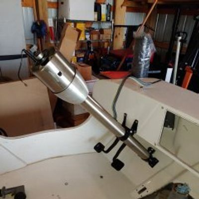
In the Body topic, I cover the installation of the steering column and steering wheel. It's worth mentioning the decision making process and the factors that helped determine the components I selected. I originally intended to use the original steering column from the CJ-5 chassis, because I liked the simplicity of the old-school look. However, I soon realized that it would take some custom fabrication to adapt that column shaft to my steering setup. I also realized that there is very limited space for entry to and exit from the driver's seat, and a tilt steering column would probably be a necessity.
Again, my search led me to Speedway Motors. I purchased an ididit GM-style, 33" tilt steering column with a brushed finish, integrated turn signal and hazard provisions, and a pre-terminated wiring pigtail. They also had the perfect floor and dash mounting brackets to fit the CJ. To top off the column, I purchased a Grant steering wheel that resembles an early Jeep unit, and used a Grant GM-style adapter and horn button kit.

The most complex portion of the steering system was designing the linkage from the column to the steering box. (As discussed above, the switch to the Advance Adapters Saginaw Conversion greatly simplified this task.) Due to the narrow frame rails, the location of the steering box, and the intrusion of the aftermarket headers into the available space, I needed to get creative with the design. I turned to an outstanding online resource - the Steering System Design & Tech page on the Borgeson Universal website. Borgeson has been a leader in high-quality steering components for many years, and on this page they have compiled their vast knowledge of steering design. Their design guidance covers safety, durability, vibration reduction, component options, geometries, steering ratios, and more. If you're installing a customer steering setup, be sure to check it out.